(one 256k, the other doubled to 512K)įor the binary memory contents file to be programmed:
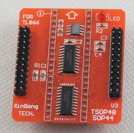
TSOP32 ADAPTER SCHEMATIC FOR TL866 ZIP FILE
NOTE I HAVE ATTACHED A ZIP file with the 2 binaries. It matched the one described (but not currently provided) by “sparx_59” / Nataf on the Badcaps website ( ). I saved the memory image to a binary file. Since the checksum is ‘correct’, I am actually not sure that the flash is bad (although it may be “slow” or ‘degraded’ as described by Sparx earlier in this forum). I was surprised that it gave consistent checksum (0x00F6_F4EA). Using the TL866/Mini pro, I read out the Atmel AT49LV002 FLASH contents several times. The Boot block/programming does not matter because the flash is used in READ mode only on the DSP board.Īfter I removed the original Flash IC with the Chip Quik, I cleaned the leads, then carefully installed it in the 32-TSOP adapter. I believe the ONLY difference is that Pin 9 (RESET# on the Original FLASH, which is unused/tied high) is now “A18” (because the new Flash has one more address bit since it is 2x the size). The new Flash, although 2x the size, appears to have comparable specs (Voltage, Timings, Access time, and Package/Pinout e.g TSOP 32 8x20mm). New Flash : Macronix MX29LV040CTI-70G (4Mbit 512k x 8) (ex:.Note that the last 4 characters are printed on the Flash chip!)
TSOP32 ADAPTER SCHEMATIC FOR TL866 SOFTWARE
Note that the TL866/Minipro software shows the checksum for the flash contents (binary file). I also used a much less expensive programmer. I wanted to provide some details in case this helps anyone. Some of the symptoms are better (but the unit is not working completely). If you need the DSP then consider replacing the ROM as detailed elsewhere. No DSP or digital functions (like DTS, Dolby, etc) are available. This functionality works for me (I only use one internet-connected source into my amp) but may not work for you. Note: even with this fix any change to the ‘source’ will cause the amp to mute until it is power cycled. Ī.Re-attach “EXT.IN” inputs to test and feed in a signalī.Power on the amp and slowly increase main volume from lowest volume.Ĭ.If this fix has been successful then you will hear sound from your speakers when the main volume is much lower that in step 1.ĭ.Having confirmed the fix, reassemble the unit (you could run it permanently without the failed DSP board).Į.Enjoy a few more years out of your amp instead of dumping it!

Į.Use a solder blob to short pins 3 and 4 of this connector. In this step we disable the mute (permanently).ī.Take off the top case (as described in the service manual)Ĭ.Unscrew the back panel (a lot of screws!)ĭ.Remove the DSP card to give access to connecter CX114 on the base PCB. The electronic mute used is not infinite, hence why the test in step 1 works. I think what was happening on my system was that because the main DSP was failing (probably due to the ROM failing as described elsewhere) the microcontroller was then muting the signal. Some are electronic and some are electromechanical (i.e. There are a couple of places in the audio signal path that the system can mute the sound. Step 2 - disable the mute which is in place G.Note if you do any other adjustment to sources at this point then you will have to power-cycle the system. phone, MP3 player, computer) ĭ.Turn up the volume to around 0dB - you should hear nothing.į.Only adjust the main volume, turning it gradually up to +18db - you should hear the EXT.IN source signal coming faintly out the speakers. Step 1 - confirm your amp has the same fault symptoms as mine had:Ī.Connect a source to the FL/FR EXT.

However I noticed that in some situations (detailed below) I could hear very faint audio coming through the amp. I found my Denon AVR2802 had failed in the way described above.


 0 kommentar(er)
